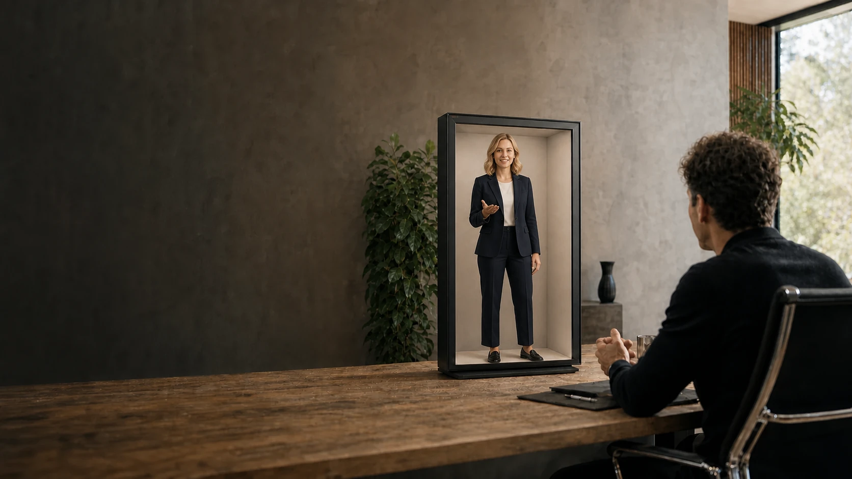
The word hologram is commonly used for almost any image that appears to float, show depth or occupy space. That shorthand is emotionally useful and technically imprecise. A reflection-based virtual image, an aerial real image, an autostereoscopic light-field display and a computer-generated hologram create different optical fields, require different source representations and fail in different ways.
Reality Relay treats them as separate endpoint classes connected by a common presence architecture. The public concept is not “one magic pane of glass.” It is a pipeline that accepts a person, object, world or AI agent; converts it into a spatially constrained scene; adapts that scene to a calibrated endpoint; operates the experience; and measures whether the result remains visually and operationally coherent.
This is a systems-level explanation of the scientific and engineering principles behind headset-free spatial presence. It intentionally stops before the unpublished optical stack-up, ray-path topology, tolerance budget, endpoint calibration solver, view-allocation policy, scene-transformation rules and recovery logic. Those are not gaps in the concept; they are where product engineering and invention begin. Nor does this article imply that every optical family described here is implemented in a single current device.
1. The target is a coherent field of perceptual evidence
A conventional display maps a two-dimensional signal to emitted radiance over a plane. A spatial-presence endpoint has a harder job: it must make the light reaching an observer consistent with the hypothesis that an entity occupies a bounded region of the room.
A useful abstraction is the plenoptic function. In a simplified two-plane parameterization, a light field is written as:
A flat image samples mainly spatial position and color. A multiview system also controls ray direction. A true holographic system attempts to reconstruct a wavefront, including phase. A convincing presence experience does not always require the most complete physical reconstruction, but it does require that the cues it presents agree with one another.
The principal cues
- Angular size and physical scale. A person must subtend a believable visual angle at the intended viewing distance. A technically sharp image at the wrong scale reads as a miniature or an advertisement.
- Binocular disparity. The left and right eyes receive different projections. Correct disparity supports stereopsis; excessive or inconsistent disparity produces visual strain or perceptual flattening.
- Motion parallax. When the observer moves, foreground and background features should change in a way that is consistent with their depth. This is one of the strongest signals that a display behaves like a window rather than a poster.
- Occlusion. Near surfaces must correctly hide farther surfaces. Depth-map holes, segmentation errors and view synthesis failures are especially visible at silhouettes.
- Focus and accommodation. The eye changes optical focus with distance. Many stereoscopic and autostereoscopic displays provide disparity while their emitted light remains focused near one physical plane, so accommodation cues can be incomplete.
- Ground contact. Feet, paws, wheels or product supports need a stable relationship to a calibrated receiver plane. Scale, support geometry and vertical placement must agree frame by frame.
- Eye line, audio direction and latency. A remote person can look geometrically present yet still feel absent if gaze, speech direction, lip synchronization or turn-taking timing is wrong.
Google’s published Project Starline research is instructive because it treated copresence as a whole-system problem: physical layout, lighting, face tracking, multiview capture, compression, spatial audio and a lenticular display were optimized together. Its evaluation reported gains over conventional video conferencing in perceived presence, attentiveness, recall and nonverbal behavior—not merely in image quality. Google Research: Project Starline
A spatial image becomes presence only when optics, geometry, time, sound and behavior tell the same story.
2. Four optical families—and why the names matter
The optical endpoint determines what kind of scene representation can be shown, which depth cues are native, where the viewing zone exists and how much calibration is required. These four families are related but not interchangeable.
| Endpoint family | What is reconstructed | Typical source | Native cues | Characteristic constraints |
|---|---|---|---|---|
| Optical-combiner / reflection | A virtual image at a designed optical location | 2D RGB or RGBA video | Scale, occlusion, perspective composition | Ambient contrast, reflected geometry, restricted depth behavior |
| Aerial real-image | A real image formed in front of an optical element | 2D image, projected surface or depth-fused sequence | Physical image location and touch-free alignment | Ghost rays, brightness, viewing angle, image-plane distortion |
| Autostereoscopic / light field | Multiple angular views emitted across a viewing cone | Multiview quilt, RGB-D or rendered 3D scene | Stereopsis and motion parallax; focus cues vary by architecture | Angular-spatial resolution tradeoff, crosstalk, view-zone calibration |
| Diffractive holography | A target optical wavefront | Complex field or computed phase pattern | Potentially rich depth and focus cues | Étendue, phase modulation, diffraction efficiency, speckle and compute demand |
2.1 Optical-combiner and reflection-based presence
A high-brightness source display can be reflected by a partially reflective optic so the observer sees a virtual image separated from the physical source. This family includes stage-illusion descendants and contemporary hololuminescent or reflection-based displays. The source can remain ordinary two-dimensional video; the sense of volume comes from enclosure geometry, black level, controlled reflections, content composition and the relationship between image, frame and floor.
This can create powerful human-scale presence, but it should not be described as a native multiview light field. If every observer receives essentially the same source view, moving laterally does not reveal new sides of the object. The endpoint therefore needs content that is authored for a bounded optical volume rather than content that assumes unrestricted three-dimensional navigation.
2.2 Aerial real-image systems
Aerial imaging systems form a real image in free space. One method, aerial imaging by retro-reflection, routes light through a beam splitter toward a retroreflector and back so rays converge at a plane-symmetric location. Micro-mirror array plates and dihedral corner-reflector arrays use arrays of tiny orthogonal reflectors to form an image on the opposite side of the plate.
The image can occupy a physically useful interaction plane, but optical efficiency, ghost paths and distortion become first-class design variables. Published Optica work on micro-mirror array plates describes how unintended internal reflections create visible ghosts and how angular illumination and diffusers can trade brightness against ghost suppression. Optica: ghost reduction in aerial imaging
2.3 Lenticular, lenslet and grating-based multiview displays
An autostereoscopic display directs different pixel samples toward different horizontal or two-dimensional angles. A lenticular sheet uses cylindrical lenslets; a parallax barrier selectively blocks rays; a diffractive grating steers wavelength-dependent angles; integral-imaging systems use lenslet arrays to reconstruct a sampled light field.
A common content representation is a quilt: many camera views packed into one image or video frame. Each tile is a conventional perspective view. The optical transform interlaces those tiles at subpixel scale so different viewing directions receive different images. Looking Glass publicly documents this tiled representation and the device-specific parameters used to map quilt views to a calibrated light-field display. Looking Glass: quilt representation
If a panel has a fixed pixel budget, emitting more angular views leaves fewer samples per view. This is the central spatial-angular tradeoff: apparent depth and view continuity compete with per-view resolution, brightness and rendering throughput. Compressive light-field research, including tensor displays, shows that optics and computation can be co-designed to approximate richer directional fields from multilayer or time-multiplexed hardware. ACM: Tensor Displays
2.4 Computer-generated holography
In strict optical terms, holography reconstructs a wavefront. A spatial light modulator encodes amplitude, phase or a combination; coherent illumination diffracts from that pattern; propagation produces the desired field. The renderer therefore solves an inverse wave-optics problem rather than simply drawing perspective images.
This can, in principle, provide correct wavefront curvature and accommodation over depth. It also introduces hard engineering problems: finite modulator pixel pitch limits diffraction angle; finite aperture limits field of view and eyebox; coherence produces speckle; high-resolution phase patterns must be computed at interactive rates; and color requires wavelength-aware design. Calling every floating image “holographic” erases these distinctions and makes integration requirements impossible to reason about.
3. The end-to-end presence pipeline
Reality Relay separates the source, scene, endpoint and session so each can evolve without forcing every application to be rebuilt. Conceptually, the pipeline has eight stages:
- 01AcquireVideo, RGB-D, multiview capture, a 3D scene or an AI-generated asset
- 02ReconstructSegment the subject, estimate depth or geometry, recover material and motion
- 03PackageDefine scale, coordinate system, bounds, timeline, interactions and fallback
- 04ValidateCheck support geometry, safe depth, frame occupancy, motion and endpoint compatibility
- 05AdaptChoose a renderer and transform the scene for the target optical profile
- 06TransportMove synchronized media, depth, pose, audio, events and control state
- 07PresentDrive calibrated display, optics, audio and sensors as one endpoint
- 08ObserveMeasure health, drift, latency, playback, operator actions and recovery
The scene package is the critical abstraction. It is not just a video file. It is a contract between content and physical space. A conceptual manifest might contain:
{
  "representation": "video | rgbd | multiview | mesh | live",
  "coordinateSystem": {"units": "meters", "up": "+Y"},
  "bounds": {"width": 0.72, "height": 1.78, "depth": 0.38},
  "support": {"mode": "standing", "groundPlane": "space.floor"},
  "renderIntent": {"scale": "human", "background": "optical-black"},
  "interaction": {"gaze": true, "voice": true, "touch": false},
  "fallback": {"mode": "approved-loop"},
  "evidence": {"source": "recorded | generated | simulated"}
}
The exact production schema can change. The important idea is stable: a scene declares what it needs, while an endpoint profile declares what it can do. Compatibility is computed before playback, not guessed after the audience arrives.
4. Calibration turns a display into a spatial instrument
A monitor can tolerate small geometric errors because the image is expected to live on the panel. A presence endpoint cannot. A few millimeters of optical, camera or floor-plane error can make feet float, cause a face to shear across viewing angles or separate an aerial image from the intended interaction location.
4.1 Camera calibration
A pinhole camera maps a three-dimensional point P to an image point p through intrinsic and extrinsic parameters:
Real lenses add radial and tangential distortion, so calibration estimates distortion coefficients and refines them by minimizing reprojection error. Zhang’s widely used planar method derives constraints from several views of a known flat pattern, then applies nonlinear maximum-likelihood refinement. That approach matters because a deployable presence system needs repeatable field calibration, not only laboratory metrology. Microsoft Research: flexible camera calibration
4.2 Endpoint and optical calibration
For a multiview endpoint, a calibration profile may include panel resolution, view count, angular pitch, lens or grating slope, optical center, subpixel layout, view-cone direction and inversion. The final shader maps a quilt sample to a physical subpixel and an outgoing ray direction. If any of those values drift, the observer sees crosstalk, view flipping, moiré or discontinuous parallax.
For a reflection or aerial endpoint, the profile instead describes source-to-optic geometry, image-plane location, reflection transform, usable aperture, viewing zone and the physical receiver plane. Those parameters produce a transform from scene coordinates to emitted content coordinates. The adapter may need to pre-warp the source so the image appears rectilinear after the optical path.
4.3 Photometric calibration
Geometry alone is insufficient. The chain also needs a photometric model:
- source electro-optical transfer function and black level;
- channel gains and a color-correction matrix;
- spatial luminance uniformity;
- view-dependent brightness and color shift;
- polarization state where reflective or diffractive optics require it;
- ambient-light measurement and a permitted operating envelope.
The goal is not merely color accuracy. It is stable separation between the subject and the optical background. Raised blacks expose the image plane; clipped highlights flatten facial material; inconsistent brightness across angles makes the object appear to flash as the observer moves.
5. Rendering: from one scene to the rays the endpoint needs
The renderer is endpoint-specific. A two-dimensional optical-combiner Space may need a single pre-warped view with an alpha or black background. A multiview Space needs a set of cameras distributed across an angular baseline. A holographic endpoint needs wave propagation. The platform must preserve the scene’s intent while changing the emitted representation.
5.1 Multiview rendering
For a scene rendered from N viewpoints, camera centers can be placed along a baseline around a common convergence plane. Each view renders the same world from a slightly shifted origin. The views are then packed into a quilt and optically interlaced according to the endpoint calibration.
The disparity of a point provides a useful first-order relationship:
Large baseline increases depth separation but also increases disocclusion, view-to-view change and the risk of uncomfortable disparity. The practical baseline and convergence plane therefore belong to the endpoint profile, not to the source asset.
5.2 RGB-D and depth-image-based rendering
RGB-D represents each pixel with color and estimated depth. A renderer back-projects the pixel into three-dimensional space, then reprojects it into a target view. This is efficient, but newly visible regions have no source data. Those disocclusions require layered depth, temporal information, a second camera or learned completion.
MPEG’s multiview-plus-depth work formalizes a similar idea: transmit texture and depth from a limited number of source views, then synthesize intermediate views for an autostereoscopic display. MPEG: depth-image-based rendering
5.3 AI view synthesis
Neural reconstruction can infer a compact three-dimensional representation from sparse cameras or even a single two-dimensional stream. NVIDIA researchers have demonstrated a triplanar neural representation that renders a life-size talking head from novel viewpoints and drives both tracked stereo and light-field displays. NVIDIA Research: AI-mediated 3D video conferencing
AI reduces capture requirements, but it adds a new failure class: temporally unstable geometry, identity drift, hallucinated occlusion and gaze correction that looks plausible in one frame but inconsistent across viewpoints. A presence pipeline must therefore treat inference confidence and fallback behavior as runtime state, not hide them inside a renderer.
6. Grounding is a spatial constraint
Humans are unusually sensitive to support. A figure that is vertically misplaced by a small amount can appear to hover even when every facial detail is photorealistic. Grounding must be constructed from three coupled variables:
- Support geometry: identify which pixels or mesh vertices are meant to touch the floor or another object.
- Calibrated receiver plane: map that support set to the physical floor plane of the target Space.
- Temporal coherence: maintain the relationship through motion, compression, view synthesis and dropped frames.
If the support point slides while the figure remains still, separates during a step or changes between synthesized views, it becomes evidence against the illusion. The validator therefore needs support-plane distance, lateral drift and frame-to-frame motion metrics.
The same rule applies to products, animals, characters and abstract forms. Floating can be intentional, but it must be declared in the scene contract and remain geometrically stable relative to the calibrated Space.
7. Live presence is a synchronized distributed system
A recorded scene can be optimized offline. A live person requires the entire pipeline to operate under a latency and synchronization budget while preserving identity and expression.
7.1 Capture and reconstruction
A capture endpoint may combine color cameras, depth sensors, microphones and head or eye tracking. The frames need a common clock, known intrinsics and extrinsics, exposure agreement and a consistent color space. Reconstruction can then fuse geometry, segment the participant, estimate a surface or layered depth representation and correct the eye line for the remote viewer.
Google’s current Beam description uses six cameras and an AI video model to merge standard streams into a three-dimensional representation for a light-field display. The public description also emphasizes real-time head tracking. Google: Beam technology overview
7.2 Transport
A live session may carry color, depth, alpha, pose, audio, interaction events and control messages. Each stream has different loss sensitivity. Audio continuity is often more important than perfect video continuity; pose can sometimes tolerate an unreliable low-latency channel; scene-control commands require ordered delivery and acknowledgement.
WebRTC provides standardized real-time media and data channels, encrypted transport, congestion control and NAT traversal through ICE, STUN and TURN. It also exposes statistics needed for adaptation and diagnosis. Its jitter-buffer controls make the fundamental trade explicit: more buffering protects against network variation but increases playout delay. W3C: WebRTC Recommendation
7.3 The latency budget
End-to-end delay is the sum of multiple queues and transformations:
A robust system timestamps every stage, measures percentile latency rather than only the mean, and degrades deliberately. When bandwidth falls, it may reduce angular views, spatial resolution or background detail before sacrificing audio continuity, subject identity or control safety.
8. Physical AI adds behavior to the optical stack
An AI agent is not a video file. It perceives, reasons, speaks, generates motion and may call tools. Giving it spatial presence requires a boundary between the nondeterministic agent and the deterministic endpoint runtime.
The agent can propose speech, gesture, gaze target, expression or scene changes. A presence policy checks those proposals against the role, audience, interaction state and physical bounds. The renderer then converts approved behavior into animation and audio. The endpoint runtime remains responsible for timing, safety, interruption, fallback and recovery.
This separation prevents a model timeout from becoming a frozen public figure or a hallucinated tool call from becoming a physical action. If the agent becomes unavailable, the runtime can move to an approved idle behavior, disclose the state, preserve operator control and recover without pretending that the session is healthy.
9. Runtime, capability negotiation and repeatability
The final difference between a compelling prototype and infrastructure is repeatability. A production presence system should be able to answer, before a session starts:
- Does this scene representation match this endpoint’s optical adapter?
- Are the required display, sensors, audio devices and compute paths available?
- Is the endpoint calibrated, and has the profile drifted outside tolerance?
- Is the content inside permitted scale, depth, luminance and motion bounds?
- What is the safe fallback if the network, agent or renderer fails?
A deterministic lifecycle can be expressed as:
Capability negotiation is especially important across mixed endpoint families. A scene with a full multiview quilt may play natively on a lenticular display, derive a center view for a reflection-based Space or fail closed if the intended depth cues cannot be preserved. The adapter should never silently convert an incompatible scene and label the result equivalent.
Operational telemetry
Useful telemetry spans optics, media and operation:
Optical
calibration age, crosstalk, luminance uniformity, black level, view-zone confidence, ground-plane error
Media
frame cadence, dropped frames, decode time, audio/video skew, depth confidence, reconstruction stability
Session
time to ready, end-to-end latency, recovery time, fallback entries, operator interventions, completion state
A crosstalk measure can be written as the luminance leaking from an unintended view divided by the luminance of the intended view:
That final qualification matters. A single marketing number cannot describe a spatial display. Resolution, crosstalk, brightness, field of view and depth range all depend on viewing angle, content frequency, wavelength and operating conditions.
10. What actually makes the result feel real
Maximum apparent depth is not the objective. Coherent depth is. A restrained scene with correct scale, stable silhouettes, natural gaze, stable support and low latency usually produces stronger presence than an exaggerated scene that breaks at the edge of its viewing zone.
The most important design choices are often architectural rather than spectacular:
- place the entity at a believable human or object scale;
- keep the complete body or product inside the usable optical volume;
- design the physical frame as part of the room, not as decoration around a screen;
- control ambient light so the image retains material contrast;
- align the virtual and physical floor;
- use motion that respects the bounded space;
- preserve eye line, voice direction and conversational timing;
- show system state honestly when intelligence or connectivity is degraded.
11. Where the public map ends
The established science explains the ingredients. It does not determine the final composition. Some of the most consequential work sits between disciplines—where an optical system becomes a calibrated place, a generated scene becomes a stable identity and an intelligent agent becomes a trustworthy physical presence.
That frontier is defined by a small set of difficult questions:
- How can a physical frame remain optically bounded while receding from attention?
- How can one presence retain its identity across endpoints that emit fundamentally different fields of light?
- How can sparse capture produce missing viewpoints without temporal drift or invented behavior?
- How can many Spaces share a repeatable perceptual coordinate system instead of behaving like isolated displays?
- How can intelligence adapt to a place while the endpoint remains deterministic, observable and safe?
The answers depend on how optics, calibration, representation, inference and control are composed—not on any single component viewed in isolation. Reality Relay is intentionally not publishing that full composition. The public architecture can be examined; the exact route from captured signal to convincing arrival remains inside the product boundary.
The system should be explainable. The final illusion should keep one secret: how completely distance disappeared.
12. A platform approach to an evolving optical field
No single optical architecture dominates every application. Reflection-based endpoints can make large, high-contrast human figures practical with conventional content. Aerial systems can place an interaction plane in free space. Lenticular and grating-based light-field displays add directional views and shared parallax. Diffractive holography pursues fuller wavefront reconstruction. Each moves a different boundary among view count, resolution, brightness, depth, field of view, compute demand and physical form.
The durable layer is therefore the system around the optics: explicit scene representations, calibrated endpoint profiles, adapter-specific render paths, measurable runtime behavior and safe integration with live people and AI. That is the technical meaning of a presence platform.
Reality Relay architecture
Platform + Spaces
Reality Relay Platform packages, validates, adapts, operates and observes presence. Relay Space, Relay Frame and Relay Box are distinct optical architectures rather than size tiers. The platform does not erase those optical differences; it makes them explicit and operable.
Explore Reality Relay PlatformPrimary sources and further reading
- Lawrence et al., “Project Starline: A high-fidelity telepresence system,” ACM Transactions on Graphics, 2021.
- Google, “Google Beam: Our AI-first 3D video communication platform,” 2025.
- Stengel et al., “AI-Mediated 3D Video Conferencing,” ACM SIGGRAPH Emerging Technologies, 2023.
- Wetzstein et al., “Tensor Displays: Compressive Light Field Synthesis Using Multilayer Displays with Directional Backlighting,” ACM TOG, 2012.
- Looking Glass, “What is a Quilt?” technical documentation.
- Kurihara and Bao, “Ghost reduction and brightness enhancement of aerial images using lens diffusers in MMAP,” Optics Continuum, 2024.
- Zhang, “A Flexible New Technique for Camera Calibration,” IEEE TPAMI, 2000.
- W3C, “WebRTC: Real-Time Communication in Browsers,” Recommendation, 2025.
- MPEG, 3D-HEVC and MV-HEVC reference material for multiview-plus-depth and synthesized views.